Monday, September 20, 2021

Ramification at {0, ±√3}

For some purposes it is preferable to have ramification points that are equally spaced in the geographic metric, for example, ramification points located at {0, ±√3} (see diagram above) rather than at {0, 1, ∞}. These will not be Belyi functions, but will have analogous uses. For example, if the three points of ramification are equally spaced around the real-number great circle, their colors can be permuted without the geographic distortion found in four of the vertex-color permuting Belyi functions.

Therefore, it may be desirable to find the unique Mobius transformation, S, that maps {0, 1, ∞}, respectively, to {-√3, 0, √3}; and its inverse, S-1, as well. It is easier to start with the inverse since it is a mapping to {0, 1, ∞} like we saw in the previous post, in this case:

z0 = -√3

z1 = 0

z = √3

S-1(z) = ((z-z0)*(z1-z))/((z-z)*(z1-z0))

= ((z+√3)*(-√3))/((z-√3)*(√3))

= -(z+√3)/(z-√3)

= (-z-√3)/(z-√3)

So: a = -1; b = -√3; c = 1; d = -√3

From Michael P. Pitchman's web chapter on Mobius transformations:

So, S(z) = (√3*z-√3)/(z+1) = √3*(z-1)/(z+1

Domain-coloring visualization of S:

Domain-coloring visualization of S-1:

Domain-coloring visualization of their composition (Identity):

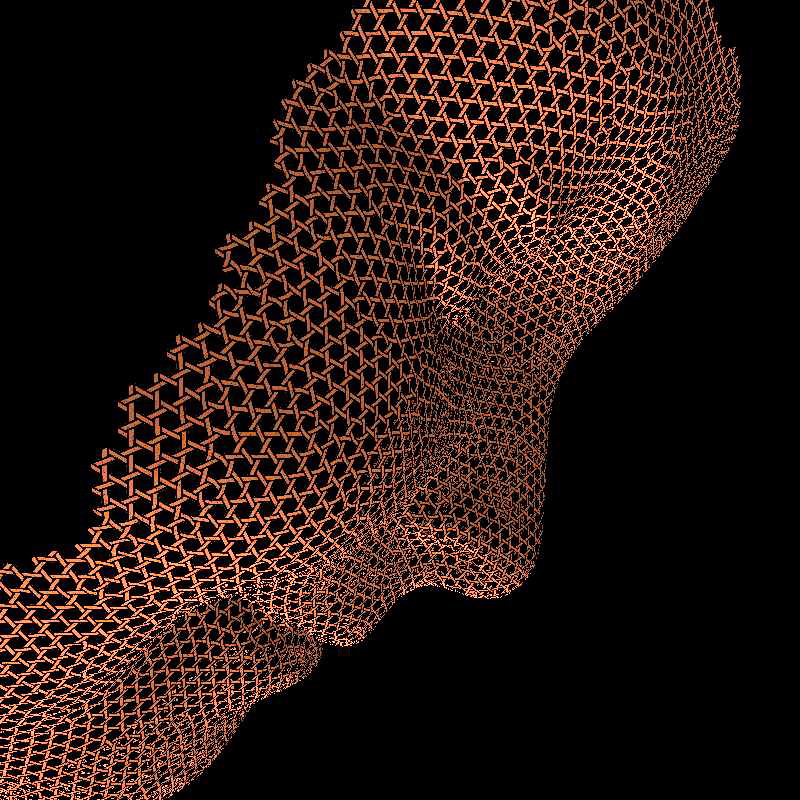
Domain-coloring visualization of S∘Tetrahedron∘S-1:

In the above view of a tetrahedron, the North Pacific now represents vertices, Antarctica now represents mid-edges, and the Sahara represents face centers. It's easy to see that there are four faces (Sahara's) and six edges (Antarctica's), but the four vertices (North Pacifics) are harder to see.

Mobius maps to {0, 1, ∞}

Belyi functions are unique up to Mobius transformations, which are conformal maps from the Riemann sphere to the Riemann sphere that preserve, not merely infinitesimal circles, but all circles. The fate of any three distinct points determines a Mobius function. A particularly simple case is when we know which three points will map to 0, 1, and ∞. Namely, we seek a Mobius transformation S, such that:

S(z0) = 0

S(z1) = 1

S(z) = ∞

Then S = ((z-z0)*(z1-z))/((z-z)*(z1-z0)).

For example, the vertex-color permuting Belyi functions can be derived this way.

Thursday, September 16, 2021

Belyi functions that permute vertex colors

The canonical triangulation of a dessin has vertices of three colors: black for original vertices, white for edge centers, 'star' for face centers. The simplest Belyi functions that permute these colors in the 6 possible ways are the 6 transformations Coxeter, in Regular Polytopes, gave as an example of the operation of the symmetric group on three elements:

Here's what they look like in geographic domain coloring (geographic conventions same as previous post.) All these functions describe a half-edge or brin in different positions/orientations: its black vertex is in each case coincident with Antarctica, its white vertex coincident with Null Island.

Identity, z:

Dual, 1/z:

1-z:

z/(z-1):

1/(1-z):

(z-1)/z:

Geographic Domain Coloring & Belyi functions

Domain coloring is a popular way to visualize functions that map the complex plane to the complex plane (equivalently, the Riemann sphere to the Riemann sphere). The range space (the plane or sphere the function maps to) is given a patterned coloring and those colors are mapped back to the domain space (the plane or sphere the function maps from) by evaluating the function at every pixel in the domain. This of course involves evaluating the function a million times or so, but computers make it easy.

For the image above, the function (-64*((1/z)^3+1)^3/(((1/z)^3-8)^3*(1/z)^3)), a Belyi function for the tetrahedron, is interpreted as a Riemann-sphere to Riemann-sphere mapping. The range Riemann sphere was decorated with a map of the globe oriented in a particular way: South Pole at 0, North Pole at ∞ (on the Riemann sphere, ∞ is the point antipodal to 0,) and Null Island (shorthand for the point off the coast of Africa at 0° latitude, 0° longitude) is at 1 (on the Riemann sphere, 1 is halfway around from 0 to ∞.) The picture below shows the range sphere in the same projection used above.

Imagine the two polar projections to be hinged at 1, then imagine closing them together like a face-down book to form a two-disk map of the world.

Always keep in mind that domain coloring produces a view of the domain. In other words, the Belyi function begins with the hollow, non-physical, decorated sphere in the top picture, and stretches and folds it, in perfect registration, to cover the globe in the bottom picture. Pretty remarkable!

The dessin, in this case a tetrahedron, is found by tracing in the domain (top picture) all the pre-images of the line segment [0,1] in the range (bottom picture). This geographic domain coloring makes: vertices correspond to Antarctica's, faces correspond to Arctic Oceans, and edges to Antarctica-to-Antarctica sea voyages that pass between two copies of Africa.

Thursday, June 17, 2021

Weave-like meshing

Computer graphics has come a long way toward generating surface meshes reminiscent of basket weaving. The image above illustrates (on the right) the technique of authors Wenzel Jakob, Marco Tarini, Daniele Panozzo, and Olga Sorkine-Hornung, called Instant Field-Aligned Meshing. To me the meshing has an almost musical quality.

Using isometries in design and fabrication

There's a cool new paper by Caigui Jiang, Hui Wang, Victor Ceballos Inza, Felix Dellinger, Florian Rist, Johannes Wallner, and Helmut Pottmann. Would you have believed an independently-designed, sleek, freeform shape like in the picture above could be assembled from a small alphabet of curved surface patches? The secret is to allow the patches to bend isometrically, that is with constant intrinsic (Gaussian) curvature--as thin shells naturally tend to do--vastly extending the design space of a small set of tools. Bravo!

Thursday, May 27, 2021

Customizing TPMS to fit

A recent paper on 3D printing is likely also relevant to 3D weaving: "Strong 3D Printing by TPMS Injection" by Xin Yan, Cong Rao, Lin Lu, Andrei Sharf, Haisen Zhao, and Baoquan Chen. The authors show how to modify a level-set approximation of a triply-periodic minimal surface (TPMS) to custom fit the shape and interior stress levels of a sculptural object. Alison Grace Martin has already demonstrated that many TPMS can be woven.

Tuesday, May 25, 2021

Twisting weaving strips to low aspect ratios

Low aspect ratios (quarter-twist-wavelength over strip-width) are possible if the metal is relatively thick and twisted under high tension. In the picture, an aspect ratio of 0.77 achieved with 0.022" thick soft copper (0.096"/0.125").

The thicker the weaving elements, the larger the engagement window, eventually a locking interference is reached.

The weave pattern of a triangular helix

The stereogram shows a portion of the woven D-surface built up along the axis of a single triangular helix, that is, built above one of the triangles in this diagram,

The triangle is small, in the view along the axis the weaving elements appear to be engaging a single point.

Since each weaving element in the helix engages only two others, this is not really a weave structure that can hold together. By comparison, in a "Star-of-David" arrangement of 6 triangular helices around a hexagon, each weaving element engages four others. This is might be the smallest "tower" that can be bult along the isometric axis if the weaving elements are held by their own friction.

Monday, May 24, 2021

The NbO net as a kagome-like packing of triangular helices

The straight lines in the D-surface form a NbO (niobium monoxide) net, which is usually illustrated from this perspective.

But viewed along a body diagonal of the cube (an isometric axis that foreshortens the the three primary directions equally) it has an kagome-like aspect. In this view it can be seen as an arrangement of triangular helices. The handedness of these helices is arranged as below:

I've made wire model to demonstrate this.

Here is a direct-view stereogram of the finished model:

Friday, May 21, 2021

D-surface weave-crossing in copper

These twisted 0.25" copper strips have a twist half-wavelength of 0.65", for a quarter-wavelength/strip-width aspect ratio of 1.3. (The hexagonal opening would be smaller in a completed weaving-- here the crossings are held together by elastic bands cut from the ends of 160Q balloons.)

In this view we are looking down the isometric axis giving the x,y,z Cartesian axes the same foreshortening. A chiral pair of twisted strips are aligned with each Cartesian axis, the six strips cross in a consistent over-under-over-under pattern around the hexagonal cycle. I made the strips by dangling a very heavy vise from the strip and counting turns. I found it difficult to get a consistent twist-wavelength over the length of the strip with this technique.

Wednesday, May 19, 2021

Can we cover the D-surface with straight-strip weaving?

Can we cover the D-surface with straight woven strips? This is a practical question rather than a mathematical one. Strips are developable surfaces (they lie flat on the plane without stretching) so they cannot in truth conform to any area on the D-surface. Also, even flat weaving never actually conforms to the plane nor completely covers it in a water-tight sense, but we can nonetheless weave quite dense fabrics—Skew TeePee falls far short on that measure. The pictures show Skew TeePee dressed up with twists of triangle-pleated paper with encouraging results. The aspect ratio of inter-crossing distance (aka, quarter twist-wavelength) to strip width before dressing was about 4.2, afterwards 1.7. Looks like we would need to get to 1.0 or better to see fabric densities comparable to tabby-weave baskets.

Tuesday, May 18, 2021

Skew TeePee reveals D-surface to be a weaving of twisted strips

It's hard to see the D surface in Diamond Weft, so I made another try with Skew TeePee, a sculpture made out of twisted (rather than bent) strips of copper. The twisted strips follow a straight course, and cross only strips of the opposite twist-handedness. Looking down any of the three cartesian directions, the S- and Z-twisted strips are arranged like a checkerboard.
By arbitrarily choosing to "ride along" either side of a twisted strip, the crossings are seen to alternate over and under. Presumably a large enough weaving in this pattern would hold together by friction in the usual basket way–these strips are lashed togrther at the crossings with elastic hair bands. Skew TeePee does not get very far towards closing up the D-surface, but I believe it is possible to do better with straight, flat, but more tightly twisted strips.

Friday, April 2, 2021

Lockable weaving strips via pinking-shears and hole punch

Lockable weaving strips can be made by hand using pinking shears to cut strips of the appropriate width, and then enlarging the bottom of some or all of the regularly-spaced pinking-shear notches with a hand punch. In the examples above pinking shears with 5 mm tooth spacing and a hand punch with a 1/8-inch diameter hole were used. It proved difficult to keep the pinking-shear notches perfectly in phase on both sides over an 11 inch run since multiple cuts and re-registrations are needed over that distance. The holes were aligned by eye to just barely reach the bottom of the appropriate pinking-shear notch.

The width of the pictured strips at the narrows between pinking-shear notches is 0.40", 0.65", and 0.85". These strips lock fairly loosely but can accomodate four layers at the locked crossing (as is necessary when two splices coincide at a crossing), as shown below.

Wednesday, March 31, 2021

Multiphase weaving strips for locked crossings

If all weave crossings will be locked at the same angle, the same notch pattern can be repeated with high frequency along the length of the weavers. The wavelength can be an integer divisor of the width of one crossing, for example, in the photo and the diagram below, the repetition wavelength is 1/2 the width of one locked, 90° crossing.

This allows a variety of shapes to be made with the same set of notched weaving strips since the distance between successive crossings can be adjusted to any integer number of wavelengths. On the other hand, if the strips are custom notched, any angle and spacing of crossing can be accomodated, but the strips may only be useful for the intended construction.

Thursday, March 25, 2021

Correction for engagement windows

The geometry of an oblique locked crossing is not fundamentally altered if the engagement windows are too large to be neglected. The radius, r, used in the calculation, remains the same, but the mechanical radius of the hole cut into the weaver, rm, must be made larger. If the 'thickness' of the engagement window (seen as the cross-section of a double convex lens) is t, then rm = r + t/2.

The best value for t needs to be determined by experiment, as it will depend not only on the thickness of the weaver, but also its elasticity, the desired stiffness of the joint, and how acceptable permanent plastic deformation of the weaver might be.

Geometry of oblique locked crossings

When two weavers of equal width cross at an angle, say 2θ, their area of overlap is a rhombus. If the weavers are thin enough that the engagement windows of their oblique locked crossing can be approximated as points, those four points also form a rhombus (dotted lines in diagram above) that shares the same diagonal lines as the former, but with angles slightly different—assuming the radius, r, at the bottom of the notches is not zero.

In the diagram, weavers are only indicated out to the width, 2h, where the centers of the notch radii are located. The point where the centerlines of the two weavers cross makes a natural origin for the diagram; in particular, we choose the perpendicular to the centerline at that point on our chosen weaver (the gray one) to define the line of x = 0 for our coordinates. Taking h, r, and θ as given, the geometric problem is to find the x-coordinates of the centers of the four holes (the geometry of the other weaver will be simply the mirror image of this one.)

The solution requires repeated use of trigonometric identities for geometrically similar right triangles, all having acute angles of θ and 90°-θ. Such an analysis yields these expressions for the marked dimensions indicated in the diagram:

xL = r/cosθ

xR = r/sinθ

sL = htanθ

sR = h/tanθ

The x-coordinates of the circle centers on the inner edge (upper edge in the diagram) can then be calculated from:

xL = cL - sL

xR = sR - cR

For the circle centers on the outer edge, just multiply by -1.

Tuesday, March 23, 2021

Oblique locked crossings

When weavers cross at a non-perpendicular angle, they can still be locked using four notches in each weaver.
And they engage in the same manner as for a perpendicular crossing.
The centers of the engagement windows no longer form a square (as they do at a perpendicular crossing) but a rhombus. When the notches terminate in a circular radius, the circle centers do not form a rhombus, rather a parallelogram.
The acute angle of parallelogram (and thus the acute angle of the weavers crossing) ends up being a little wider than the acute angle of the rhombus. In the diagram above, 33 degrees vs. 30 degrees in terms of half-angles. The bottom line: we can program oblique locked crossings with same shape notches used for perpendicular locked crossings, we just need to make some adjustments in their positioning along the length of the weaver.

Thursday, March 18, 2021

Sinusoidal notches for locked crossings

The best profile for the notches seems to be roughly sinusoidal, as seen in this template which I have been using with a 3/16" hole punch and strips of aluminum flashing that have been averaging 1.47" wide (I had aimed for 1.5"). The black discs are for visually centering the punch when the cardboard template is punched. Even at this relatively coarse scale of weaving the notching must be done at an accuracy that is pretty demanding for handwork (all of this could be avoided with a steel rule die to punch the whole 4-notch crossing in one blow.)
The image above shows via backlighting the four little lens-shaped openings or engagement windows that are the inevitable consequence of the material's non-zero thickness. A precise design needs to accomodate this geometry.

The fourth notch is engaged by bending the sides of both weavers upward, as in the photo below: